introduction to CSEM
Controlled
source electromagnetic Methods (CSEM)
CSEM techniques are used to investigate subsurface geological strata using electromagnetic signals generated by artificial sources. This is possible because the various subsurface strata are made up of materials with different electromagnetic properties in terms of their resistivity/conductivity and chargeability. The fact that hydrocarbons (oil and gas) exhibit different resistivities enables CSEM to be used, for example, to determine with high levels of probability whether hydrocarbon-bearing formations are present in the subsurface, and to obtain information about the geometry and extent of the reservoir.
ELECTROMAGNETIC FIELDS AND RESISTIVITY
An electromagnetic field (EM field) is a physical phenomenon produced by electrically-charged objects. It is made up of an electric field (often referred to as “E”) and a magnetic field (often referred to as “H”). In many ways, electricity and magnetism represent two sides of the same coin. A time-variant electric field acts as a source for a magnetic field, while a time-variant magnetic field acts as a source for an electric field.
The electromagnetic spectrum categorises different forms of electromagnetic signal radiation on the basis of signal frequency. For example, radio waves transmit at relatively low frequencies, and visible light at relatively high frequencies. The electromagnetic signals used in marine CSEM typically exhibit very low frequencies.

Figure showing the electromagnetic spectrum.
ELECTROMAGNETIC FIELDS AND RESISTIVITY
A field generated by an electromagnetic source will propagate in all directions (through 360 degrees) unless non-conductive insulators intervene to prevent propagation. In a theoretical vacuum, the field will propagate at the speed of light. All material substances, including air, have a given property that counters this propagation, commonly called electrical resistivity. Resistivity causes propagation of the field to attenuate (reduce in strength and velocity) the further it travels from the source.
The differences in resistivity between different materials enable us to use electromagnetic signals to map geological formations in the subsurface. When an electromagnetic field propagates through the different formations, it becomes successively influenced and modified by the resistivities of the different strata it encounters.
The resistivity of a given material is measured in ohm-metres (Ωm). Hydrocarbons exhibit relatively high resistivities, typically in the range 20 to 100 Ωm, while formation brines have relatively low resistivities, typically between 0.25 and 0.3 Ωm. There is thus a considerable difference between the resistivity of a reservoir formation containing hydrocarbons and one containing brine.
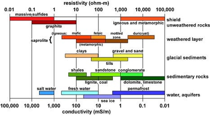
Figure showing typical resistivity values for a variety of different materials (scale along the upper x-axis). The lower x-axis indicates conductivity (the ability of a material to transport electricity), which is the opposite of resistivity.
The figure is taken from the link http://emgeo.sdsu.edu/emrockprop.html.
ELECTROMAGNETIC METHODS USING NATURAL SOURCES
Marine CSEM techniques have their precursors in methods using natural electromagnetic sources.
A method known as magnetotellurics (MT) was developed during the 1950s and can be used to investigate the geological subsurface to depths of about 100 kilometres. MT employs natural sources of electromagnetic radiation such as the sun. The purpose of such methods is to obtain greater insights into the physical structure of the Earth and how the planet has evolved. However, MT is not very suitable for investigations of the oceanic lithosphere because, among other things, natural sources transmit signals at very high frequencies that attenuate (disappear) rapidly during propagation in water.
DEVELOPMENT OF MARINE CSEM TECHNIQUES
Marine CSEM is the collective term for a number of techniques that can be used to investigate the geological subsurface using electromagnetic signals generated by artificial and controllable sources.
The development of marine CSEM techniques has been driven by the limitations associated with using MT at sea. Research into such methods was launched in the late 1970s by the Scripps Institute of Oceanography in California. Natural electromagnetic sources are replaced by artificial and controllable devices that make it possible, among other things, to control the frequency components of transmitted electromagnetic fields. In the 1980s, development was continued by a couple of small research groups at the universities of Toronto and Cambridge. The Cambridge group later moved to the University of Southampton.
Up until about the year 2000, marine CSEM remained for the most part an academic discipline, focusing on investigations of the major structures of the Earth’s subsurface, and involving only a very limited number of research scientists. It was the company Electromagnetic Geoservices ASA (EMGS) that first commercialised a marine CSEM technique for use in oil exploration. EMGS was a spin-off from the former company Statoil Innovation AS.
The development of marine CSEM for use in oil exploration was driven in particular by the limitations of seismic techniques. Marine CSEM enables the utilisation of independent geophysical parameters to indicate the presence of hydrocarbons and thus achieve significant reductions in the risks and costs associated with exploration and production.
MARINE CSEM SURVEYING
The electromagnetic field is transmitted from its source in all directions (through 360 degrees), both downwards through the water, penetrating the seabed, and upwards into the air. The receivers will record this transmitted field. What is of particular interest is measurement of the response to the transmitted field as it propagates through the geological subsurface before it is recorded by the receivers situated on or above the seabed. These response signals will be influenced and modified by the resistivity of the different subsurface formations.
Typically, electromagnetic signals are transmitted continuously from the source at one or more optimised, selected frequencies. The signals are recorded continuously by the receivers at the same time as transmission is being carried out. This technique is known as the frequency domain method, to distinguish it from the alternative time domain method.[1] The latter does not employ continuous signal transmission. Instead, signals are transmitted by the source at given intervals in the form of pulses. Measurement of the signals by the receivers is carried out preferably in the intervals between pulse transmissions, i.e. when the source is not transmitting. Using this technique, signals are not transmitted at optimised, selected frequencies, but across a broad frequency range.
CSEM SIGNAL PROCESSING AND ANALYSIS
The signals arriving at the receivers are commonly referred to as raw data, which are normally processed and analysed. The aim of processing and analysis is to find out if the received signal response deviates from that which would have been received if a hydrocarbon-bearing reservoir had not been present in the subsurface. The frequency domain method involves the use of horizontally-oriented sources and receivers. A measured deviation, in the form of a stronger and higher velocity signal than would normally be expected, will typically be the result of transmitted electromagnetic signals having been “guided” through a hydrocarbon-bearing reservoir. The time domain method employs vertically-oriented sources and receivers. In this case, a measured deviation will be due to the fact that discharge of the signal progresses more rapidly than it would have done if a hydrocarbon-bearing formation had not been present.
Processing represents the first stage of the handling of the raw data. It may involve a process called “stacking”, by which data that ostensibly belong together are gathered together with the aim of achieving a broader and more robust basis for data analysis. This is carried out in different ways depending on the CSEM technique that has been applied. For example, stacking may be performed on the basis of same frequency, or same location.
Processed data can be analysed in different ways. Currently, the most common form of data analysis is inversion. The first stage in the inversion process is to use software to construct an initial uniform half-space geological model, or a gradient-based model, that represents the anticipated geological subsurface. Mathematical models are then used to simulate the electromagnetic response that such geology would produce. These data are then compared with the response that was actually recorded by the receivers. The geological model is then repeatedly adjusted and compared with the measured response until it produces a response that coincides with, or is a close approximation to, the measured data.

This display contains information about the location of resistive formations in the subsurface.
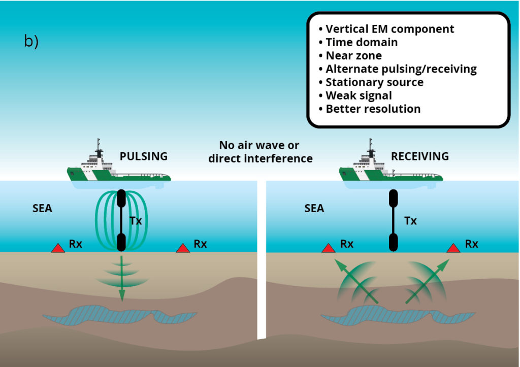
VERTICAL (TIME DOMAIN) CSEM
Vertical CSEM is conceptually different from other CSEM techniques. It is more sensitive to the presence of hydrocarbon-bearing formations, and enables us to detect such strata at greater depths. It also provides higher resolution data.
The benefits of using Vertical CSEM can only be achieved if measurements are made using stationary sources and receivers, and at short offset distances in relation to the transmitting source (near zone). Thus, in simple terms, Vertical CSEM provides good data in areas in close proximity to the source, in contrast to traditional CSEM techniques that require greater offset distances between the source and receivers.
The following five features of the Vertical CSEM technique distinguish it in particular from traditional approaches:
• measurements are made at short offset distances
• transmitters and receivers are stationary during measurement
• transmitters and receivers are oriented vertically
• signals are transmitted from the source using the time domain method
• transmitted signals are of the square pulse type
This approach makes it possible to identify hydrocarbon-bearing formations that would be difficult to pinpoint using traditional CSEM approaches, such as thin reservoirs or those buried at great depth. The greater levels of data resolution achieved using this method enable us to obtain more information about the probability of the presence of hydrocarbon-bearing formations.

This figure compares a traditional CSEM approach (left) with the vertical “TEMP VEL” method (right). In both illustrations, the source transmitter is shown as an elongated black object that is either towed behind (left) or suspended below (right) the vessel. The red symbols on the seabed represent receivers. The blue-hatched area in the subsurface indicates a hydrocarbon-bearing reservoir.
The figure above provides a comparison of equipment configurations deployed using a traditional CSEM technique and a Vertical CSEM (TEMP VEL) approach. In both figures, the green arrows provide a simplified illustration of the propagation of the electromagnetic signal from the source down into the subsurface, and then up again to the receivers. In reality, the signal propagates in all directions (through 360 degrees). However, our interest is primarily focused on that part of the signal that interacts with a potentially hydrocarbon-bearing reservoir.
In simple terms, the traditional approach (a, above) involves the “guiding” of part of the electromagnetic signal through the hydrocarbon-bearing reservoir, on condition that the signal arrives at the reservoir at a specified angle. Normally this means that the signal response that arrives at the receivers is stronger and at a higher velocity than if a hydrocarbon-bearing reservoir had not been present.
Using the vertical CSEM approach (b, above), parts of the signal propagate vertically downwards into the subsurface before the response is generated and arrives at the receivers. If a hydrocarbon-bearing reservoir is present in the subsurface, its resistivity will cause the signal response arriving at the receiver to exhibit more rapid discharging and a weaker amplitude. The change in amplitude is thus very small and is usually of the order of nanovolts.
SHORT OFFSET (NEAR ZONE) MEASUREMENTS
Using the Vertical CSEM technique, electromagnetic signal measurement is made at short offset distances from the source. The offset distance between source and receiver is selected to be short enough to meet specified near zone criteria, which in practice means that at least one receiver is placed at a distance from the source that is less than the anticipated depth of burial of the reservoir. In contrast, traditional CSEM techniques involve offset distances that are typically many times greater than the anticipated reservoir depth.
The advantage of applying near zone criteria is that the signals are measured while the signal strength is relatively high. The measurements are thus more focused, making the method more sensitive to the possible presence of hydrocarbon-bearing reservoirs in the subsurface. Moreover, this approach enables data to be recorded at higher resolution, which in turn allows us to attribute greater levels of certainty to the possible presence and geometry of hydrocarbon-bearing reservoirs in the survey area.
Using traditional CSEM approaches, which involve the continuous transmission and measurement of the electromagnetic field (frequency domain method), short offset measurements will yield no result. The reason for this is because the greater part of the signal arriving at the receivers will be derived from that part of the field that has propagated directly from the source to the receiver.
STATIONARY SOURCES AND RECEIVERS
An additional and distinctive feature of Vertical CSEM is that both sources and receivers are deployed for the most part in a stationary configuration. In practice this means that the receivers are installed on the seabed, while the source is mounted on a vessel that remains stationary while measurements are being carried out. In traditional CSEM approaches, the vessel is in motion while measurement is in progress.
A universal problem associated with marine CSEM surveying is that data that arrive at the receivers contain not only the response from the electromagnetic field transmitted from the source, but also that generated by the equipment deployed and the general surroundings. This extraneous signal is called “noise”. In order for the data to be of use, we must ensure an adequate signal-to-noise ratio. The use of stationary sources and receivers contributes towards achieving such a ratio, and this contribution is enhanced by the fact that multiple measurements can be carried out at the same location.
Data from the same location can be gathered together as part of the aforementioned “stacking” process carried out during processing. This promotes greater certainty and precision in the processed data. Data from the same location can also be gathered using techniques involving a moving vessel. This is achieved by towing the source across the same location multiple times. However, in such cases, the finally processed data is likely to be less precise because in practice all of these data will not be derived from exactly the same location.
VERTICALLY-ORIENTED SOURCES AND RECEIVERS
A distinctive feature of the Vertical CSEM technique is that it is based on a system involving the use of vertically-oriented sources and receivers (so-called VED sources and VED receivers). The use of vertically- as opposed to horizontally-oriented systems in CSEM surveying represents two quite contrasting approaches.
The laws of electromagnetic physics determine that the electromagnetic field mode is very sensitive to resistive horizontally-oriented strata in the subsurface. For example, signals transmitted from vertically-oriented sources can penetrate to much greater depths than those from horizontally-oriented sources. This makes it possible to identify hydrocarbon-bearing formations at great depths.
TIME DOMAIN METHOD
Another key feature of Vertical CSEM techniques is their application of the time domain method. As previously described, time domain methods are based on the transmission of electromagnetic signals at pre-defined intervals, while measurement takes place only during the intervals between transmission. The signals are transmitted across a broad range of frequencies. This is in contrast to frequency domain methods, which involve the continuous transmission of a limited selection of optimised frequencies, and during which measurements are also carried out continuously.
The advantage of using a broad range of frequencies is that we obtain a more diverse dataset containing information about the structural configuration of formations in the subsurface, and thus achieve greater sensitivity to the possible presence of hydrocarbon-bearing strata.
Perhaps an even more important feature of time domain methods is that the primary electromagnetic field transmitted from the source will be “exhausted” by the time the receivers are recording the response signals. This means that we will avoid the phenomenon by which the primary field masks the response signals from the subsurface. The masking effect on the response from possible hydrocarbon-bearing reservoirs by the so-called “air wave” has been a major problem associated with marine CSEM surveying. Air can be described virtually as a vacuum. Electromagnetic signals will propagate with greater velocity and strength through the air and thus will likely dominate the signals arriving at the receivers. The use of time domain methods circumvents this problem because during the intervals between the transmitted pulses, a secondary electromagnetic field is recorded, which represents the field that has propagated through the subsurface before returning upwards.
SQUARE PULSE SIGNALS
A further feature of the Vertical CSEM approach is that the transmitted electromagnetic signals are of the square pulse type. The use of such source signals is prerequisite for application of a time domain method. In contrast to sinusoidal pulses, the sharply cut-off nature of square pulse signals means that they are turned off abruptly, as opposed to being phased out.
An advantage of this is that the field transmitted from the source is attenuated more rapidly. This allows the aforementioned secondary field to be measured without masking by the primary field. In this way, square pulse signals contribute to the distinctive sensitivity of Vertical CSEM techniques to the presence of hydrocarbon-bearing reservoirs, and the recording of high resolution data.
Furthermore, square pulse signals allow us to obtain an accurate time datum for transmission of the primary electromagnetic field from the source. This makes it easier to attribute the transmitted signal to data that arrives at the receivers, which in turn allows us more easily and accurately to determine the time it takes for the secondary field generated by the transmitted field to arrive at the receivers. As described previously, it is the time-dependent amplitude of the signal transmitted from the source to the arrival at the receivers that contains information about the possible presence of hydrocarbon-bearing reservoirs in the subsurface. The fact that the use of square pulse signals enables us to obtain more precise information also allows us to investigate formations that are deeply buried in the subsurface.
An example of a sequence of alternating polarity square pulse signals is shown in the figure below. In the illustration, the positive source pole is activated for 30 seconds, followed by a 30-second interval. The negative pole is then activated for 30 seconds, followed by a new 30-second interval, and so on.